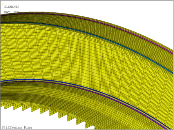
1. PROBLEM DESCRIPTION
Deacon Engineers carried out the design of large, rotating digesters for the treatment of municipal solid waste. The digesters are approximately 65m long and 4.5m in diameter and rotate continuously, at 1 rpm, while processing up to 500 tonnes of waste. Due to the cyclic nature of the loading, careful attention had to be paid to the fatigue design of the welded joints of the digesters. The standard adopted was British Standard 7608:1993 Code of practice for fatigue design and assessment of steel structures (BS 7608).
2. FATIGUE DESIGN OF WELDED JOINTS
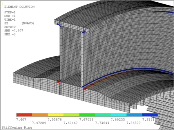
Certain digester welds were not readily classifiable according to the rules of BS 7608 because of the joint geometry and the direction of the applied stress range, which changed direction during rotation of the shell. In these situations it was highly advantageous to utilise a structural stress approach. Deacon Engineers use the Verity module in fe-safe™. The software uses forces calculated from the finite element model to generate the structural stresses for calculating fatigue lives of welded joints. The method is mesh size insensitive and does away with the ‘hot spot stress’ technique which requires a finer mesh in the vicinity of the weld toe and is subject to the discretion of the fatigue analyst.
3. OTHER APPLICATIONS
Typical equipment which is subjected to multi-axial and out of phase loading, and which needs to be analysed using the fatigue analysis techniques discussed here, are listed below:
- Kilns
- Mills
- Scrubbers
- Granulators